(C) 2008
Bob Tucker
info@zerontec.com
Introduction
Furnaces must be designed and operated to achieve:- A desired production rate
- Acceptable product quality (e.g. temperature uniformity in steel slabs, time at temperature in brick kilns)
- Maximum thermal efficiency
- Pollution emissions (e.g. NOx) within acceptable or legal limits
Because of their high temperature, furnaces are large users of fossil-fuel energy. The following simple diagram lists the main losses on a typical furnace. Flue gases usually represent the main source of wasted energy.
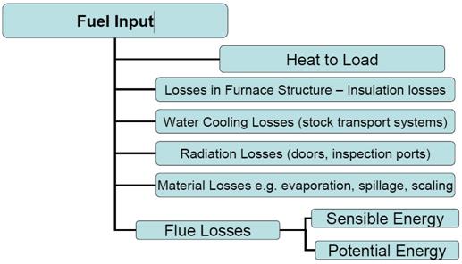 Fig. 1
Flue gas losses
Flue gases represent the main energy loss on furnaces on account of their high temperature. Sensible losses as a percentage of net heat input can be estimated from the following graph for different percentage levels of excess air:
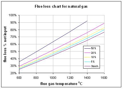 Fig. 2
Where there is poor combustion, potential losses due to the products of incomplete combustion (e.g. CO, unburnt methane) should also be added. The graph shows how important it is to maintain a low air-fuel ratio control at the burner and to minimise air leakage into the furnace. For optimum efficiency there should be typically 1-2% oxygen in the flue gases to ensure complete combustion and minimum sensible energy losses. This is equivalent to between 5 and 10% excess air.
Flue gas heat recovery
One of the most convenient and effective ways to improve furnace efficiency is to recover heat from the flue gases by preheating the combustion air supply to the burners. The flow rate of flue gases is always matched to the flow of air to the burners. Heat recovery can be achieved by installing flue gas recuperators or thermal regenerators. Fuel savings of between 30 and 50% can easily be achieved, often with pay back in less than 2 years. The chart below can be used to estimate the savings.
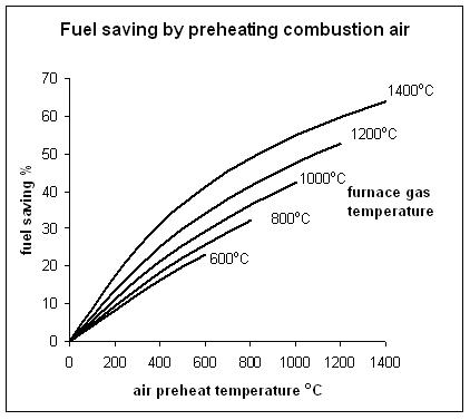 Fig. 3
Use of oxygen
Oxygen is sometimes employed on furnaces to increase production capacity. Applied as pure oxygen or used to enrich the air to higher than 21%, it displaces nitrogen in the combustion process and results in improved heat transfer and a significant reduction in flue gas heat losses. The value of the fuel savings has to be compared to the cost of supplying oxygen to the furnace.Load preheating
Where possible heat can also be recovered by preheating the load entering the furnace. This is often embodied into the design of the furnace as in continuous steel reheating or in brick kilns, where the hot gases travel in a counter-flow direction to the load. The potential heat recovery is limited in such cases by available space and by product handling issues. It is common practice to apply a combination of load and air preheating on furnaces.Insulation losses
On a well-maintained furnace, losses by heat conduction through the refractory or ceramic fibre insulated walls are quite small (<5% of thermal input). The exception to this is where the furnace is used intermittently (batch type operation) and a large amount of energy is consumed in bringing the furnace structure (the hearth, walls, roof etc) up to operating temperatures. The stored energy can then become a significant source of wasted energy. Energy losses on these types of processes can be reduced by application of lightweight ceramic fibre insulation.Other causes of energy waste
- Poor temperature control leading to:
- Possible overheating of the load
- Excessive cycling of the burners
- Poor pressure control leading to air leakage into the furnace or leakage out of hot combustion gases
- Radiation losses through openings and doors on the furnace
- Losses to water-cooled components such as water-cooled skid rails and access doors.
- Load material losses such as spillage of molten metal in foundries, metal losses due to scaling
- Losses associated with poor heating quality and low product yield.
- Poor hearth utilisation. If the furnace is oversized for the production duty, this can lead to high standing losses.
Advanced furnace technologies
The correct choice of burner system, controllers and load handling systems are crucial to achieving reliable and efficient production. Recent advances in technology include:- Direct control of load temperatures using optical pyrometers in place of thermocouples.
- Advanced control systems using mathematical models and neural networks to optimise furnace zone controls for minimum fuel use and product quality.
- ĹFlameless combustionĺ systems for low NOx control where the fuel is intimately mixed with the combustion products as it burns. This removes peaks in flame temperature and can give improved temperature uniformity.
- Impulse or sequential burner firing to achieve uniformity of heating.
- Application of high emissivity coatings to the furnace hot face insulation to increase radiative heat transfer.
Mathematical modellingBecause of the large variation in furnace design and applications, and wide range of techniques available to reduce energy consumption, mathematical models are often employed. They can identify the best options for saving energy and reduce the financial and technical risk of new investments. These models range from the simplest single zone model to advanced CFD (computational fluid dynamic) models. An example of a single zone model for investigating some of the issues above can be obtained from Zerontec Ltd (email info@zerontec.com). |
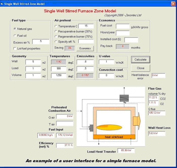 Fig. 4
|
Example 1
Assume a furnace with a net thermal input of 1MW, an exhaust temperature of 1000°C, and operating with 20% excess air. The flue losses account for 52% of the net thermal input (520kW), see Fig. 2 above. Assuming 5% other losses (50kW), then the useful heat transfer to the load equals 430kW (i.e. a thermal efficiency of 43%). What is the percentage saving by reducing the excess air to 5%?At 5% excess air, the flue losses are reduced to 46.4% (see Fig. 2 above). Assuming that Ĺother lossesĺ remain the same at 50kW, then the total heat transfer = 430kW +50kW = 480kW.
If new thermal input = F kW, the flue losses = 0.464 x F.
A simple heat balance on the furnace can be written as follows:
Heat input (F) = Flue losses (0.464 x F) + Load heat transfer (430) + Other losses (50)Thus, 0.536 F = 480
F = 896kW
The fuel saving = (1000-896)/1000 = 10.4%
In practice, the fuel saving may be higher due to the improved radiative heat transfer in the furnace.
Example 2
Taking the example above, what is the effect of adding a recuperator on the furnace?Assume a recuperator effectiveness of 35%, this could deliver air at approximately 350°C at 1000°C furnace temperature saving 19% of the fuel input (see Fig. 3).
Combining both a reduction in excess air and flue gas recuperation results in a combined saving 27.5% .
Further information
For further information on furnace technology, mathematical modelling, some latest R&D activities and forthcoming training courses please go to www.zerontec.comTraining courses on furnace technology and modelling are offered by BIFCA (British Industrial Furnace Constructors Association) in collaboration with Glamorgan University (visit www.bifca.org.uk )
See also the article on combustion