See also:
Manual meter reading;
Automatic meter reading;
Justifying additional meters
Flow metering technology
1 Meters for liquids, gases, and solids in suspension
The scope of this section is very broad because of the wide range of substances being measured, and the fact that any one metering technology will often be applicable to several different substances. The term ‘liquids’ would encompass water and non-aqueous fluids such as oils, but these could be at elevated temperature or pressure, have aggressive materials dissolved or suspended in them, or be carrying entrained air bubbles for example. They might be in the form of a slurry. Gases might also be at any temperature or pressure and they, too, may have solid material suspended in them (either as minor contamination, or as transported product). Steam is a particular example of a gas with properties that make it hard to meter.Table 1 provides a rough guide to the technologies applicable to various classes of measurement. In the paragraphs which follow, more detail is given on each technology. The table should only be used as a rough guide because numerous local factors peculiar to each case need to be taken into account. It is always worthwhile asking your supplier to help you make the most appropriate selection, or to confirm the meter you have already chosen is suitable for the duty. Reputable suppliers are usually happy to provide advice because it is sound business sense to help their customers avoid mistakes.
The typical questions that need to be answered are :
- What liquid or gas is being measured?
- What is the expected temperature range?
- What is the maximum expected pressure?
- What maximum and minimum flow rates need to be accommodated?
- What is the maximum acceptable pressure drop?
- In some cases, how much straight pipe is there upstream and downstream?
- In some cases, is electrical power available?
- If measuring a liquid, what is its viscosity? Is the viscosity likely to vary significantly?
- What is the state of the measured liquid (dust, dirt, bubbles, etc.)?
| Measured fluid | ||||||||
|---|---|---|---|---|---|---|---|---|
| Meter type | Clean gas |
Dust- laden gas |
Steam | Clean liquid |
Dirty liquid |
Viscous liquid |
Slurry | Com- pressed air |
| Orifice | A | A 3 | A | A | ||||
| Pitot | A | B | A | A | ||||
| Variable area | B | A | A | A | ||||
| Venturi | A | B | A | |||||
| Nozzle | A | A | ||||||
| Target | A | A | A | A | A | |||
| Positive displacement | B | B4 | A | |||||
| Diaphragm | B | |||||||
| Weir | A | A | ||||||
| Turbine | B | B | A | A | ||||
| Multi-jet | B | |||||||
| Vortex | A | A | A | A | A | A | ||
| Electromagnetic | A 1 | B1 | A 1 | B1 | ||||
| Ultrasonic Doppler | A | A | A | |||||
| Ultrasonic time-of-flight | A | B | ||||||
| Coriolis | A | A | B | A 2 | ||||
| Thermal mass | * | A | A | A | B | A 2 | B | |
1. Only conductive liquids; 2. Limited applicability; 3. Turndown limit 4:1; 4. Higher pressure loss than alternatives
Turbine metersA freely-spinning propeller rotates in the gas or liquid flow, and the number of revolutions is counted. A typical turbine meter uses a multi-bladed rotor supported by bearings in the pipe section, perpendicular to the flow. Fluid drives the rotor at a speed proportional to the fluid velocity and thus to the overall volume flow rate. In some models, the propeller drives the readout via a gear train; in others a magnetic coil outside the pipe produces an alternating current as each blade cuts the magnetic flux, each pulse representing a specific volume of fluid. The rotor may be made of stainless steel to resist corrosive fluids. However, the bearings are susceptible to damage from dirt or particles in the fluid and must always be in good condition to allow free rotation of the rotor at all speeds. The potential for bearing damage often imposes a temperature limitation on turbine meter operation and may make them unsuitable for applications such as compressed air where sudden pressure shocks are a risk.Turbine meters are available in a wide range of sizes, from 15mm to 500mm diameter piping. They give a fast response and provide high accuracy, subject to the bearings being in good order (the main factor limiting the life and reliability of the instrument). The meters may be supplied as full bore devices or "insertion" types, in which the diameter of the turbine is less than a full pipe bore. The latter measure the fluid velocity by "sampling" a part of the fluid flow; they are sometimes used in systems where the full pipe diameter is very large, but they wear out quickly and are not accurate over long periods. One limitation of the turbine meter is its sensitivity to viscosity. A meter calibrated in water will not read the same in a fluid of different viscosity. |
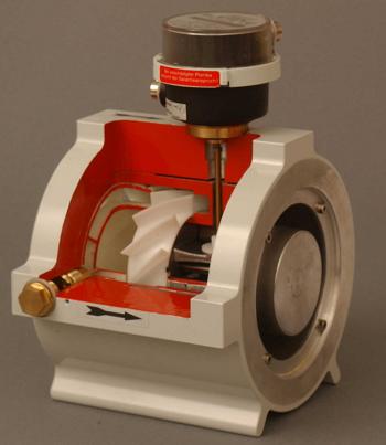 Fig. 1 |
Fan or jet meters
A meter of a similar type is the fan or multi-jet meter. Here the rotor is mounted at right angles to the fluid flow and the fluid strikes the rotor tangentially. These meters are generally limited to measuring hot and cold water, for which they provide good accuracy at a moderate price.
Diaphragm metersThis pattern of gas meter is very common in domestic, commercial, and small industrial gas installations. It is limited to low-pressure use only and is unsuitable for very high gas flow rates. Figure xx shows the mechanism, which consists of a pair of chambers each divided into two compartments by a diaphragm which works, in effect, like a double-acting piston engine driven by the differential pressure of gas entering and leaving the meter. The two diaphragms oscillate out of phase, driving a crank which in turn operates the readout register. |
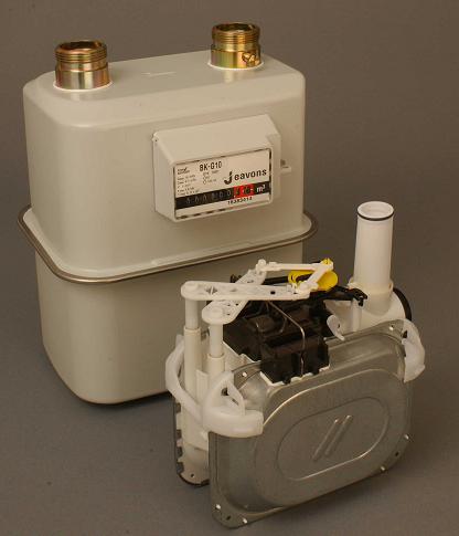 Fig. 2 |
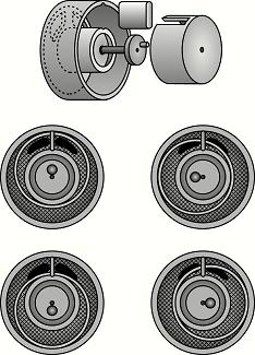 Fig. 3 Fig. 3
|
Positive displacement metersVarious patterns of "positive displacement" device are available for metering liquids. Figure 3 (left) is a case in point. Here, an annular chamber is divided by a partition between inlet and outlet ports. The inlet is on the left, and liquid, shown shaded, passes anticlockwise to the outlet on the right. As it does so , it carries with it an eccentrically-mounted hollow cylindrical piston. This is the mechanism used in many small water and oil meters, being supplied in capacities down to 5 ml/s. |
| For more accurate liquid metering, a device of the pattern shown in Figure 4 would give accuracies down to 0.1%. The body is fitted with a rotating barrel equipped with four vanes. These slide in and out radially, but are connected in opposite pairs to maintain a seal against the inside of the meter body. Liquid entering at the top left rotates the barrel anticlockwise as it passes through to be discharged at the top right. |
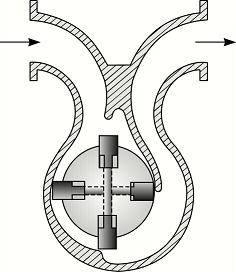 Fig. 4 |
| There is also a whole class of "gear" meters similar in principle to Figure 5, in which the measured liquid or gas turns contra-rotating elements. The Figure-of-eight pattern shown is only one of many shapes; they range from toothed to oval, and include various, more complex, interlocking forms. They can be very accurate, with high turn-down ratios, but may be prone to jamming on entrained dirt particles. Once jammed, they cut off the supply. On gas supplies, sudden increases in demand will cause temporary pressure loss while the meter’s moving parts accelerate. This may adversely affect the metered equipment. |
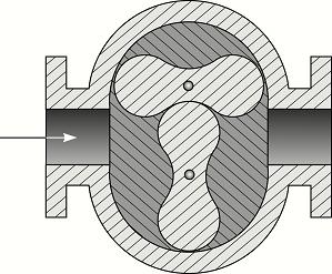 Fig. 5 |
Orifice plates
The orifice plate illustrated in Figure 6 relies upon the pressure drop across the restriction as an indicator of flow rate. This is a simple, rugged device giving an accuracy of perhaps 2% of full scale over a 4:1 turndown ratio. It is relatively cheap (especially in larger sizes) and easy to install but requires regular checks to maintain serviceability. It calls for installation in a long, straight section of pipe (typically 20 diameters upstream, five downstream) and erosion of the orifice itself can badly affect calibration. This will be a problem when measuring saturated steam (because of entrained water droplets) or dust-laden air.Like all pressure-drop metering devices the orifice plate needs a differential pressure (DP) cell, from which the signal may be fed to a flow recorder, or other equipment designed to compensate the flow reading for changes in temperature and pressure.
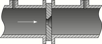 Fig. 6
When the orifice plate is used for steam measuring and the plate is fitted in a horizontal line, there is a possibility of condensate building up against the upstream face of the plate. To prevent this, a small hole can be drilled in the plate at the bottom of the pipe. This hole also serves to allow small particles of dirt to pass through and is therefore sometimes useful when using a plate to measure liquids containing minor quantities of suspended materials.
There are many different types of orifice plate available. For most flow plates involving gases, air, steam and water, the square-edged orifice plate is normally used. Other designs with conical-edged orifices, or with segmental or annular orifices, are used for special applications, such as liquids with higher viscosities or with erosive properties, or where there is substantial risk of material build-up.
There are several ways of mounting orifice plates. With orifice flanges, the pressure taps are drilled into the flanges which are welded or screwed onto the pipe. Carrier rings may be used, in which case the orifice is inserted between the rings which are drilled for the pressure taps. The entire assembly is then mounted between flanges. Prefabricated pipe runs with flanges and taps already assembled are also available.
Nozzles
The nozzle (Figure 7) is an alternative orifice meter more capable of handling gases with abrasive burdens, and liquids containing suspended solids which are not sticky. Having no critical sharp edges its calibration will not be changed by the cumulative effect of such material. It will handle approximately 60% higher fluid flow at the same pressure drop as a conventional orifice plate. It is moderately easy to install, and cheaper to maintain than a simple orifice plate. Like the orifice plate it needs 20 diameters of straight pipe upstream.Nozzles can give better accuracy than orifice plates, typically ±1% to ±2% of full scale.
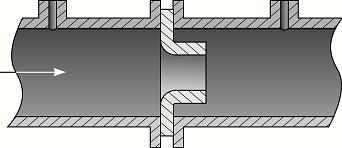 Fig. 7
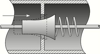
Variable Area Orifice MetersOne of the limitations of orifice-type meters is their relatively small turn down ratio. They give a non-linear output, which restricts the range of flows across which they will work accurately. This problem is addressed in variable-orifice meters (Figure 8). In this device, an orifice is partly closed by a profiled conical plug which can move axially against a spring. As flow rates (and hence differential pressure) increase, the effective cross-sectional area of the orifice also increases, resulting in a more linear relationship between flow rate and differential pressure. The Spirax Sarco 'Gilflo', which works on this principle, claims a 100:1 turndown ratio, with an accuracy better than 1% of actual flow being maintainable over a 20:1 turndown.Variable-area meters are easy to install, and do not require any minimum length of straight upstream pipe. They have moderate maintenance costs. |
|
Venturi Meters
Where the pressure drop of an orifice plate or nozzle cannot be tolerated, the venturi meter (Figure 9) in which flow rate is inferred from pressure drop in the throat of a constriction, provides higher accuracy with low resistance to flow and is relatively proof against the effects of entrained particles. Venturi meters need 5-20 diameters of straight pipe upstream, are moderately easy to install, and have low maintenance costs. Venturi tubes exhibit a very low pressure drop compared with other differential head meters but they are the largest and most costly for a given flow rate (although total installed cost may not be much higher than other meters). Various types of venturi are made, including cast sections with most or all of the interior machine smoothed, welded assemblies, and rectangular-duct versions.Applications are generally limited to those requiring low pressure drop and high accuracy reading. They are often found in large diameter pipes such as those in water and waste water treatment plants because their gradual narrowing and opening shape allows solids and sediment to pass through easily. Their shape also allows satisfactory use on services such as air with suspended solids.
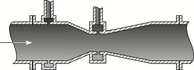 Fig. 9
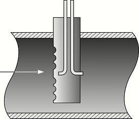
Pitot TubesThe pitot tube relies absolutely on steady flow conditions, and requires a straight upstream pipe length of 30 diameters. The pitot may for example consist of two concentric tubes, as shown in Figure 10, with a hole in the outer tube facing upstream and one hole in the nose of the pitot which leads to the inner tube. The fluid flow impacts on the hole which is placed facing upstream but not on the other holes. This means there will be a difference in pressure between the nose hole and the other, this difference being a function of the velocity of the fluid.Pitot tubes are generally moderately priced. Because of their small size, they create little pressure drop in the pipe. They are more useful for applications where a temporary installation is required: in many cases, they can be inserted for a spot check and withdrawn for use elsewhere. For the highest accuracy, they should be inserted and measurements taken at prescribed intervals across the entire flow area. Indeed, such a traverse should be repeated along various diameters at prescribed angles to the original traverse and the data must be properly averaged. Various forms of pitot tubes have been developed into meters. One example is the "averaging" pitot tube or Annubar (Figure 11). This consists of a diamond shaped strut that spans the pipe with several impact holes along the length of the strut on the upstream side and one on the downstream side. This arrangement gives an average differential pressure reading across the pipe, from which the flow is computed. For all its simplicity, the pitot tube has the disadvantage of a low turndown (say 5 to 1) and it is sensitive to the swirling of the fluid in the pipe. For accurate readings, it must be used and installed with care. The upstream or ‘impact’ hole should be pointed directly upstream for accurate results, but minor deviations from this are not normally significant. |
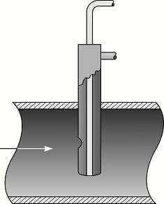 Fig. 10
|
Target Meters
Because not all the fluids one needs to measure will be clean enough to measure with a high-precision meter, there is a place for more robust devices. Figure 12 illustrates a "flap" or "target" meter which provides a way of measuring dirty or corrosive liquids, or gases with entrained dust particles. A plate which partially obstructs a pipe is subjected to a pressure dependent on the gas flow. Compared with the orifice plate, this pattern of meter has less demanding requirements on installation (10 diameters upstream) and can give better accuracy with a wider turndown ratio; but it typically imposes twice the pressure drop, and has a lower maximum operating pressure.
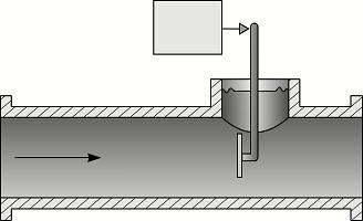 Fig. 12
Vortex Meters
When a fluid flows around a bluff object, eddies are shed downstream, alternating from side to side. The frequency of vortex shedding is directly proportional to fluid velocity. A vortex meter consists of a bluff body in the fluid flow path, together with a sensor to detect the vortex-shedding frequency and associated signal-conditioning electronics. These meters are easy to install and cheap to maintain, but require 10-20 diameters of upstream straight pipe. They have a good turn-down ratio, long-term repeatability and good accuracy because they have no moving parts. They are not unduly sensitive to wear on the bluff body.Electromagnetic Meters
This technique can be used only on electrically-conductive liquids and slurries, but has the great advantages of zero pressure drop and tolerance to virtually any kind of contamination, high viscosity, and aggressive chemical characteristics. A magnetic field is maintained across the direction of fluid flow, and in accordance with Faraday's law, generates a voltage across the width of the liquid at right-angles to the magnetic field. This voltage, which is directly proportional to fluid velocity, is fed into a signal conditioning unit and thence to an integrator. Electromagnetic meters are easy to install (requiring only 5 diameters of straight pipe upstream) and have low maintenance costs. They can in principle be used for measurements in open channels, provided that there is a continuous measurement of liquid surface level to combine with the velocity signal.Ultrasonic Meters
These meters share the electromagnetic meter's tolerance of aggressive fluids, impose no pressure drop, and are unaffected by changes in viscosity. They work on one of two principles: either measuring the doppler shift of ultrasound echoed from entrained particles or bubbles within the fluid, or measuring the transit time of an ultrasound pulse projected to a downstream sensor across the flow (or in some cases reflected back to the transmitter side).Time-of-flight meters tend to be more accurate but they do not tolerate bubbles in the measured flow. Doppler meters on the other hand require bubbles or particles in the flow or they will not work.
They are very easy to install (even on live pipework) but require about 20 diameters of straight pipe upstream and 10 downstream. They can be virtually maintenance-free.
Portable Doppler meters are available which can be very convenient for temporary measurements. These often need to be sited in places where there is not enough straight pipe, in which case the manufacturers recommend experimenting with different positions around the pipe circumference, using the signal strength to detect the position with the most stable flow conditions.
Coriolis Meters
These meters come in a variety of forms, but generally consist of a vibrating tube whose behaviour changes in response to changes in mass flowrate. In one pattern, illustrated in Figure xx, the fluid flows through a vibrating U-tube and sensors measure the angle through which the end of the U-tube twists under the influence of alternating forces imposed by the moving fluid.Having no internal obstructions, coriolis meters are not only tolerant of aggressive fluids but are also easily cleaned, making them suitable for food, chemical and pharmaceuticals measurement.
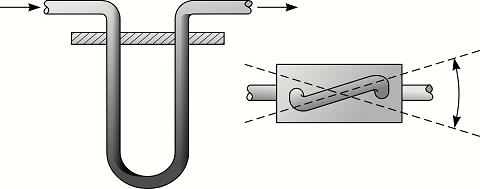 Fig. 13
Thermal Mass Meters
Thermal mass meters consist of a small, low-power thermostatically-controlled heating element. The measured fluid cools the element at a rate proportional to its velocity, and by measuring the power supplied to keep the element at its set temperature, the flow rate can be inferred.These meters are expensive, but easy to install, with no requirement for straight upstream pipework; and they have low maintenance costs.
WeirsFor dirty liquids, especially in large volumes, the notched weir (Figure 14) is a good candidate. Liquid entering at (1) settles in compartment (2), passing under a baffle to compartment (3), from which it overflows through a notch (4). The level of liquid rises with increased flow in a way which depends upon the shape of the notch, the height of liquid surface being registered via float (5). The V-shaped notch illustrated is used when there are large variations in flow rate; for more even flow rates a square notch can be used. |
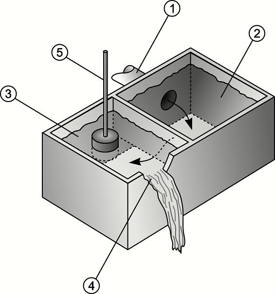 Fig. 14 |
Batch Weighing
Liquids may be difficult to measure for reasons other than entrained matter: for example, they may be corrosive or sticky. Corrosive character can be addressed through appropriate choice of materials in the design of the meter; but where stickiness is a problem, batch weighing may be the only answer, treating the material like a solid (but tare-weighing the container to account for adherent residues).Summary of flowmeter features
Table 2 indicates some of the salient properties of different types of flow meter in general terms. It is important to stress, however, that individual applications will differ, and that the achieved accuracy can be critically dependant on the quality of installation.Table 2: Significant flowmeter properties
| Type | Advantages | Limitations | Range | Typical error |
|---|---|---|---|---|
| Orifice | * Low cost | * Low turn-down | 4:1 | ±2% to ±4% FS |
| Pitot | * Ease of installation | * Only samples local flow velocity | 5:1 | ±3% to ±5% FS |
| Variable area | 20:1 | ±1% to ±10% FS | ||
| Venturi | 3:1 | ±1% FS | ||
| Nozzle | * Tolerates entrained particles | 3:1 | ±1% to ±2% FS | |
| Target | * Tolerates entrained particles | 10:1 | ±1% to ±5% FS | |
| Positive displacement | * High accuracy | * Entrained particles may jam the meter and shut off flow |
10:1 | ±0.5% R |
| Diaphragm | * Limited pressure * Cannot handle high flow rates |
±% to ±% FS | ||
| Weir | * Tolerates dirty liquids | * Open channel flows only | 100:1 | ±2% to ±5% FS |
| Turbine | * Clean fluids only | 20:1 | ±0.25% R | |
| Multi-jet | 10:1 | ±2% R | ||
| Vortex | * Low pressure drop | 10:1 | ±1% R | |
| Electromagnetic | * Little upstream and downstream straight pipe required * No pressure drop |
* Only works on conductive fluid | 40:1 | ±0.5% R |
| Ultrasonic Doppler | * No pressure drop * Portable versions |
10:1 | ±5% FS | |
| Ultrasonic time-of-flight | * No pressure drop * Portable versions |
20:1 | ±1% to ±5% FS | |
| Coriolis | * Tolerate suspended solids * High accuracy |
10:1 | ±0.4% R | |
| Thermal mass | * Low pressure drop | 10:1 | ±1% FS |
FS full scale
R reading
2 Heat Meters
When heat is distributed through a hot water or thermal fluid loop, the temperature of the returning fluid is lower than the flow temperature. The heat delivered is proportional to the flow rate multiplied by the temperature drop (or rise, in the case of a cooling loop). Modern heat meters also use what is called a “floating K factor” to account for the temperature-related change in specific enthalpy1 of the fluid.Heat meters therefore integrate a flowmeter with two temperature measurements.
The installation criteria are driven by the kind of volumetric flow measurement used in the meter (see above). Accuracy depends not just on the volume measurement but also on the differential temperature measurement. Matched platinum-resistance temperature sensors would typically be used for sensing the temperature, because high accuracy is needed. Otherwise, at low power, serious inaccuracies would arise because the differential temperature could be of the same order as the temperature measurement error. Calibration is therefore particularly important for applications such as space heating, where sustained low load operation is likely. Furthermore, when measuring heat flow into or out of an extensive loop or network, there may be transient errors caused by time lags through the monitored loop; the return temperature will not respond immediately to changes in heating or cooling load. Fortunately, this effect is negligible when the meter-reading interval is much longer than the delay time.
When retrofitting heat meters the effects of pressure drop must not be ignored. The new meters may upset the balance of the network (if manually balanced) and may even restrict the heat flow in an unacceptable fashion. Appropriate measures will need to be taken, such as re-balancing the system after installation of the meters or using a low-pressure-loss flow metering element. Indeed many modern types of heat meter use non-invasive flow-sensing elements, and provided that these are not sized at less than the pipe bore, system balance will not be affected.
3 Solids Measurement
When it comes to the measurement of solids, be it coal (for example) or the products of industrial processes, the method used depends upon the form of solid. Broadly speaking, solids can be categorised under three headings:- formed items
- particulate
- suspensions
Volumetric measures can be used, but the bulk density of particulate material may increase if it settles during transit, while entrained air or even static electricity can have the opposite effect. Some solid powders are too fine in texture to carry on open conveyors and these are commonly carried in pipes, suspended in a current of air. In effect, the powder suspension acts like a fluid and a coriolis mass flow meter could be used, for example. To cope with solids in suspension, a meter has to be proof against erosion, which rules out orifice plates and any device with moving parts.
The venturi meter is promising in these cases because of its relatively streamlined flow path. One of its variants, the Graczyk meter, is specifically adapted to the task by having an additional downstream pressure tapping. Two pressure differentials are recorded, one from the upstream to the throat, and the other from upstream to downstream. The first gives the gas flow rate, while the ratio of the two gives the solids loading. The annular form of the meter is less affected by upstream disturbances such as pipe bends.
Other resources
See relevant product pages for ABB Flow Measurement ProductsFor steam metering see Spirax Sarco learning centre